Magnetic Field Generation for Tau Disaggregation in Alzheimer's Disease, Part 1: Motivations and Magnetic Field Generation
Hello! It’s been a couple of months since my last journal entry, but I’ve been working on one of my most ambitious projects yet: a DIY magnetic field generator!
This summer, I will be interning at the USC Mann School of Pharmacy in the Seidler Lab, studying pharmaceutical approaches to disaggregate Tau fibril filaments in the context of Alzheimer’s Disease (AD). While planning an innovative approach to this complex challenge, I stumbled upon the potential of magnetic fields.
At first glance, it might seem like a bad idea—placing a magnet near your arm. Do you feel your arm being attracted to the magnet? Not unless you’re wearing a neodymium cuff! Biological systems are not very susceptible to magnetic fields. This can be beneficial: for example, Magnetic Resonance Imaging (MRI) uses field flux densities (which can be thought of as field strength, since the magnetic force scales with flux density) of 0.5-3 Tesla, yet patients aren’t ripped apart.
However, recent studies indicate that magnetic fields can have subtle effects on biological systems, especially over long periods. One paper by Weiler M, Stieger KC, Long JM, Rapp PR (2020) conducted a meta-analysis of studies examining the impact of low-frequency alternating magnetic fields on memory and cognitive function in AD patients and found improvements in many of the studies.
Another study by Darwish, S. M., & Darwish, I. M. (2022) investigated the impact of Static Magnetic Fields (SMF) on tau at the conformational level, finding that even weak magnetic fields (0-2.2mT) could shift absorption band peaks in Fourier Transform Infrared Spectroscopy in the amide IV and V regions, corresponding to side-chain and tertiary structures. This suggests changes in the magnetic moments within tau residues, implying changes in bond angles or lengths, presenting the possibility of leveraging SMFs to create fibril instability.
Perhaps the most promising and least investigated mechanism for disaggregating tau fibrils via magnetic fields is magnetomechanical therapy. Magnetomechanical effects arise from magnetic nanoparticles (typically iron-oxides) in a biological region of interest that are exposed to a low-frequency alternating magnetic field. The study by Nikitin AA, Ivanova AV, Semkina AS, Lazareva PA, Abakumov MA (2022) discusses the mechanisms for these magnetomechanical effects, as well as their application in, most notably to my project, deforming DNA strands (I will most certainly be returning to this study in the next article to examine further).
I wanted to investigate the implications of both SMF and AMF, so I set out to find a way to generate each. The issue is, an electromagnet setup with both SMF and AMF capabilities is expensive. To stay within my budget, I built my own setup.
Coils
For my coil selection, I chose the Heyiarbeit 12V 1200N pulling force solenoid electromagnet from Amazon, priced at around $35. The main advantage of buying such an electromagnet instead of wrapping copper magnet wire around a bobbin is the presence of a core. The magnetic field flux density of a solenoid coil in a vacuum (or approximately in air) can be calculated as: $$ B = \frac{\mu_0 NI}{L} $$
Where (B) is the magnetic flux density in Tesla, (I) is the current in amperes, (μ0) is the vacuum permeability, (N) is the number of turns, and (L) is the length of the solenoid in meters. However, if the solenoid is surrounded by a magnetically susceptible core such as iron, the equation becomes: $$ B = \frac{\mu_0 \mu_r NI}{L} $$
Where \( \mu_r > 1\) is the relative permeability of the core material. This coefficient encapsulates the enhanced magnetic permeability of magnetically susceptible materials over air, which can increase flux density by orders of magnitude.
A core must fit the coil design to optimize flux density enhancements. For that reason, it is much more viable to purchase the coil online than to buy magnetic wire, bobbins, core material, etc., and then manipulate them to get a functioning coil.
Coil Setup
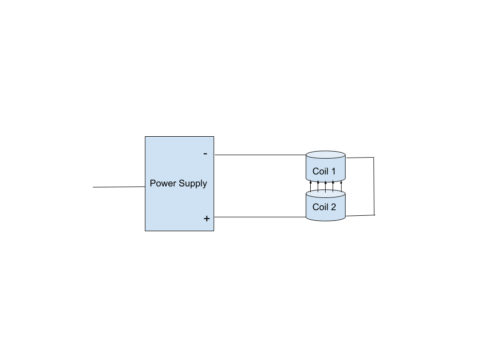
To enhance the uniformity and strength of the generated magnetic field, one can arrange two electromagnet coils in a pseudo-Helmholtz configuration, with current flowing in opposite directions through each coil to create opposing polarity between them. I chose to position the electromagnets very close (1-1.5 cm apart) to maximize central field flux density.
Experimentally-determined Coil Parameters as determined by multimeter and LCR meter:
- Combined inductance: L = 205mH
- Total Resistance: R = 23.9 Ohms
SMF Components
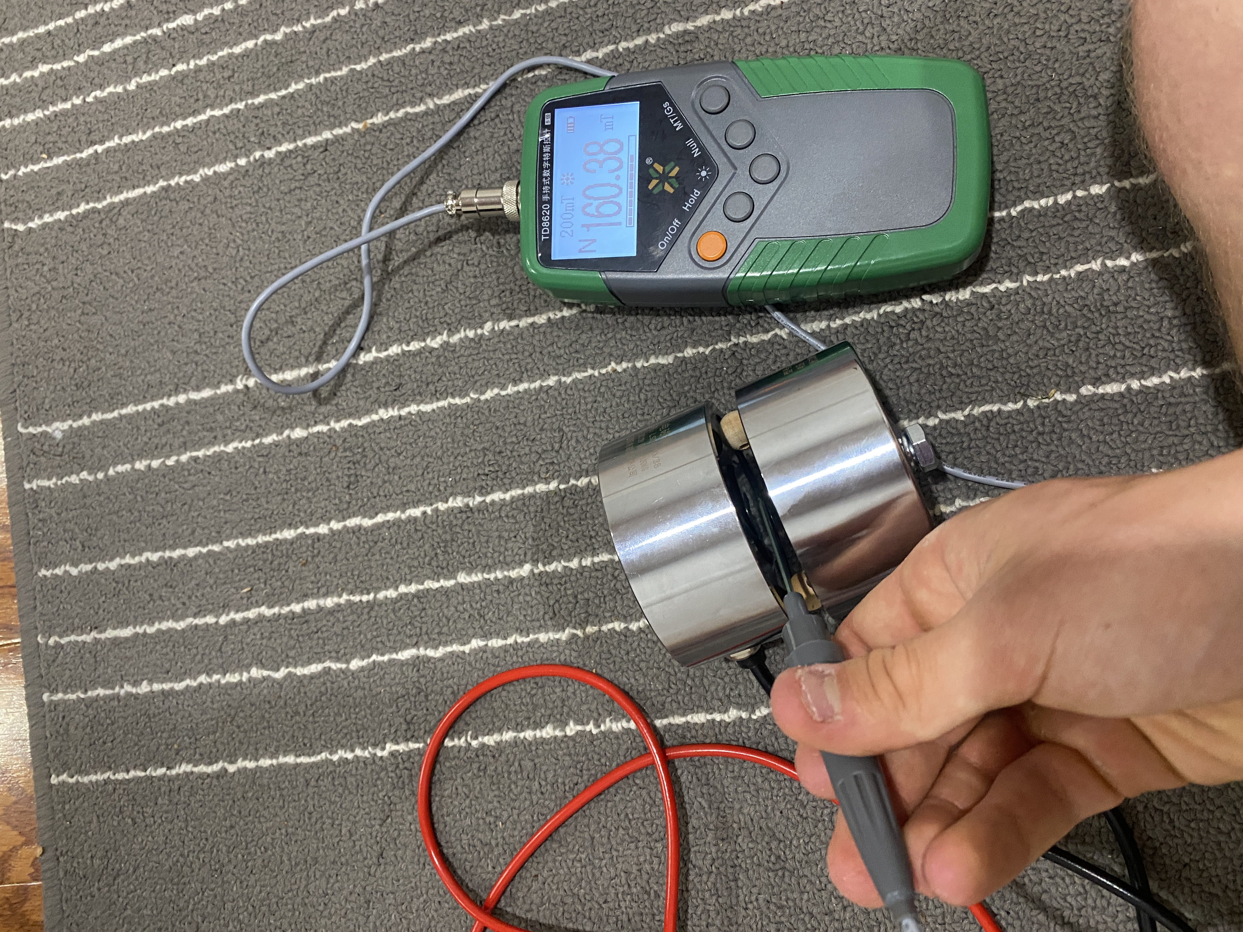
An SMF setup (Figures 1 and 2) is generally simple to accomplish once you have some coils to work with. It requires only a variable power supply, some wiring, and maybe a fuse for safety.
Currently, I’m facing some power dissipation issues in the DC circuit. Namely, while each coil seems to perform without significant heating effects at 12V for long periods of time, exposure to 21V and 0.85A (which is less than the theoretical maximum of 12 + 12 = 24V) in the pseudo-helmholtz configuration appears to create significant heating effects in a short period of time and increasing resistance in the coils (thus decreasing current). According to my power supply, the power dissipation in the circuit when these effects are observed is approximately 17.5W. Nonetheless, for a short period of time, I’m able to produce an approximately 160mT central field flux density in the SMF setup.
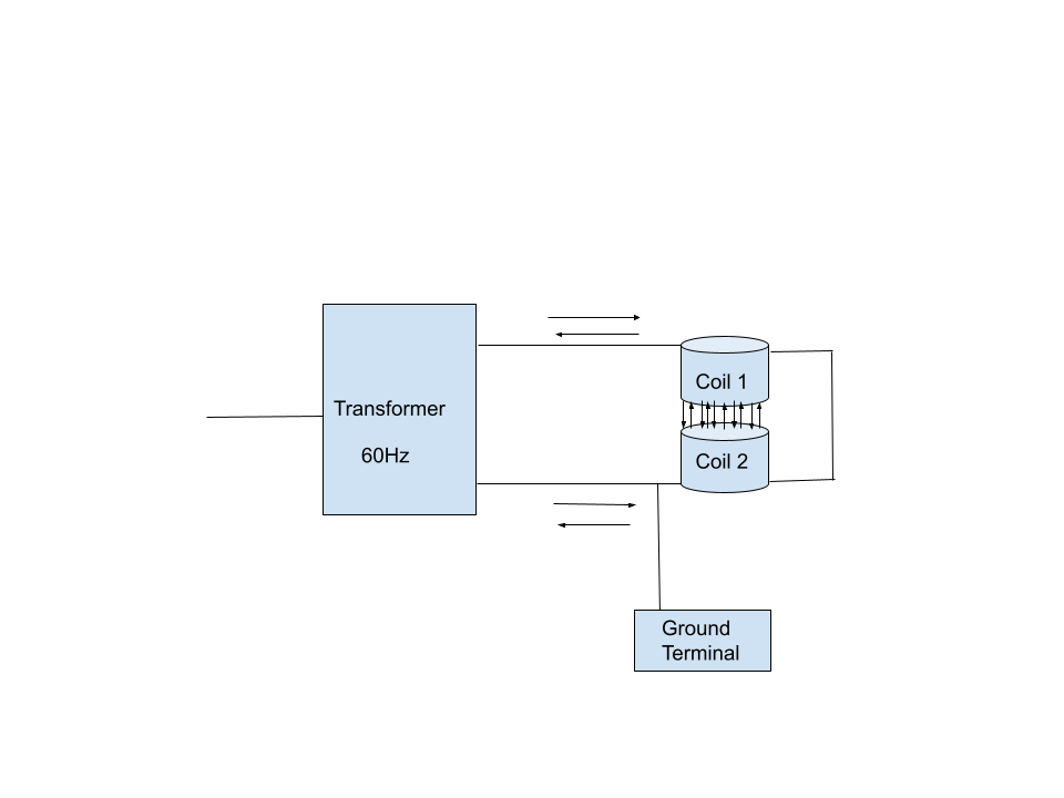
AMF Components
An AMF setup (Figures 3 and 4) is not as easily achieved as the SMF setup. Initially, I wanted to control the frequency at which the current alternates in Hz, but that would necessitate a function generator and an amplifier, both of which can be pricey and perhaps unviable for a high school student with little to no previous experience in electronics. Given that most studies investigating the magnetomechanical effects of nanoparticles (NPs) in AMFs operate within a frequency range of less than 100Hz, I decided to select a single frequency within this range to test. Any electrician would likely agree that the simplest frequency to implement in this range would be 60Hz, as the AC frequency in home outlets is 60Hz. Therefore, all I needed was a transformer to allow me to vary output voltage in my AC circuit design, with a set frequency output of 60Hz, which was far cheaper and easier to implement.
There were a few more challenges with the AMF setup as well. For instance, I was unsure that I could generate any significant AMF strength at all due to the increased impedance of inductors (i.e., magnets) when fed AC. In a DC circuit, total impedance (Z) is equal to the equivalent resistance (R) of the circuit. Thus, per Ohm’s law, current in amps in the circuit, is expressed as:
$$ I = \frac{V}{Z} = \frac{V}{R} $$
Where (V) is voltage in volts. However, in the case of an AC circuit with an inductor, the inductor will resist changes in current to oppose changes in magnetic flux (per Lenz’s law), so there will be an extra element to total impedance of the circuit. This extra element is quantized as the imaginary component of impedance, otherwise known as reactance. Reactance in ohms is expressed as:
$$ X_L = 2 \pi f L $$
Where (L) is the inductance of the inductor in henries and (f) is the frequency in Hz. Then total impedance is given as:
$$ |Z| = \sqrt{{X_L}^2 + R^2} $$
So the current through an inductor in an AC circuit is reduced, potentially significantly depending on inductance and applied frequency. Since the previously-shared equation for magnetic field flux density depicts current as scaling linearly with current, such a drop in current would compromise magnetic flux density. To make sure I could generate a sufficiently powerful AMF, I needed to know the combined inductance of the electromagnet coils, so I bought an LCR meter off Amazon. According to my measurements, the total inductance of my Helmholtz electromagnet setup is 205 millihenries, making total impedance 80.89 ohms. To generate the peak magnetic field flux density as I did in the DC design, I’d need to drive 68.76V across the circuit, while my electromagnet coils are only rated for a combined 24V!
The silver lining is that, I’ve found that the voltage rating is more of a power rating in disguise. Since these electromagnets were designed for DC usage, the combined 24V rating for both coils is meant to keep power dissipation below a certain threshold, 17.5W, as previously calculated.
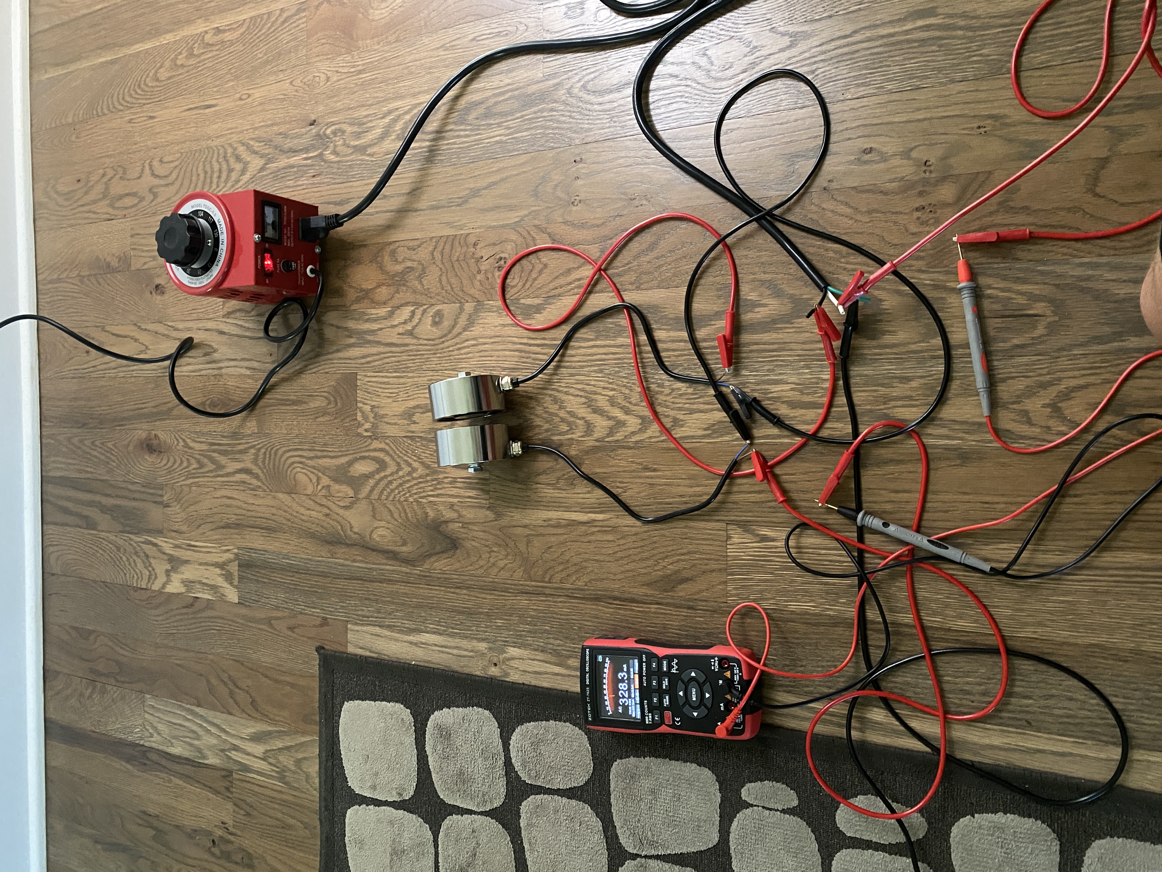
In an AC circuit, the current in the circuit is constantly changing, so power dissipation is smaller for a given peak current or voltage in the AC waveform. The ‘Root Mean Square’ (RMS) of peak AC can be used to find the equivalent DC for the purpose of examining power dissipation in the AC circuit. In the case of a pure sinusoidal waveform for AC, which I’ve confirmed is the type outputted by my transformer with an oscilloscope, that corresponds to dividing peak current in the AC circuit by a factor of (√2). Additionally, increased total impedance (due to an increase in inductive reactance) tends to lower current through the AC circuit. Although, increased impedance in the circuit, (Z), replaces (R) in the DC circuit power equation, thus offsetting some of the power dissipation reduction. With an impedance of 80.89 ohms, to stay within the bounds of the power maximum:
\frac{P}{Z} = 0.465 A RMS
corresponding to 0.71 A peak current. Therefore, I can safely drive a voltage of:
$$ V = 0.658*80.89 = 53.21V $$
across both coils without exceeding the theoretical power dissipation maximum.
The ratio between maximum peak magnetic field flux density in the AMF setup, and maximum flux density in the SMF setup should be the equal to the ratio between maximum current in the AC and DC circuits, since flux density scales linearly with current. Therefore, the theoretical maximum peak flux density achievable in my AMF setup is:
$$ B_{AMF} = B_{SMF} * \frac{I_{DC}}{I_{ACpeak}} = 160mT * \frac{0.658}{0.85} = 123.81 mT $$
Conclusion- For Now
There’s still so much I want to explore in this area of study, this article was just intended to showcase my design for the necessary circuitry to make it achievable. The next article will focus more on the possible mechanisms of magnetomechanical effects and SMF exposure, and in a few months, when I have access to lab materials such as tau protein samples, hopefully I’ll have tangible results for you all!
References:
Weiler M, Stieger KC, Long JM, Rapp PR. Transcranial Magnetic Stimulation in Alzheimer's Disease: Are We Ready? eNeuro. 2020 Jan 7;7(1):ENEURO.0235-19.2019. doi: 10.1523/ENEURO.0235-19.2019. PMID: 31848209; PMCID: PMC6948923.
Darwish, S. M., & Darwish, I. M. (2022). Spectroscopic investigation of tau protein conformational changes by static magnetic field exposure. Journal of Physics Communications, 6(7), 075004. https://doi.org/10.1088/2399-6528/ac7d3a
Nikitin AA, Ivanova AV, Semkina AS, Lazareva PA, Abakumov MA. Magneto-Mechanical Approach in Biomedicine: Benefits, Challenges, and Future Perspectives. Int J Mol Sci. 2022 Sep 22;23(19):11134. doi: 10.3390/ijms231911134. PMID: 36232435; PMCID: PMC9569787.